
Getting Lilikoi ready for sale, I decided one thing that would really help the sale is adding shore power. For the last 40 years this boat has had an extension cord running through the companionway. I figured it’s about time, and I have the parts and an electrical engineering degree, so time to do something about it.

Some adult supervision is important in any project involving electricity
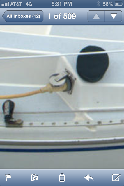
This web photo helped me decide where to place the power entry
Beginning with the shore power inlet, I had a plastic Marinco outlet from the wrecker for $25 and I needed to figure out where to put the inlet.
I did some research on the web and found a boat that had the inlet located below the winch. I checked my boat out and reached under the port berth to where the screw heads are and forward to the proposed area and found it was pretty clear. The Marinco instructions call for a 2-7/8″ hole saw. Right! I found a 3″ saw at Harbor Freight and went to town after looking at the gasket to make sure it would cover a 3″ hole. I taped the proposed plate location and made sure it wouldn’t interfere with winch operation. I wasn’t sure how thick the fiberglass is at that point (turns out to be surprisingly thin at about 1/8″ and it cut through in under 3 minutes. I had been worried that maybe I should get an expensive bimetal hole saw set, but the $10 set did the job fine.
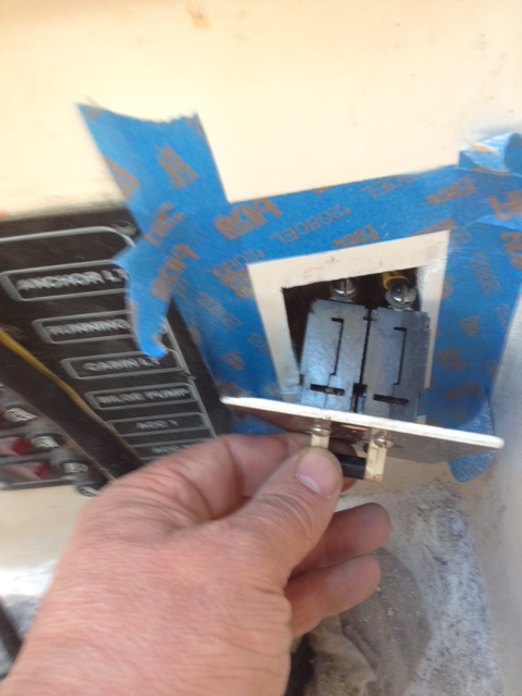
This is the depth of the breaker. I later cut the access out bigger to accommodate a full depth box to contain the wiring
I bought a dual pole 20A breaker set for $5 at a boat wrecker (they typically cost about $100). A trip to home depot to find some suitable wiring boxes. The ones I chose have ears in the front and brackets that tighten against them with a couple of Philips head screws.
The wiring needs to support the size of the breaker, so I was commited then to using more costly 12gauge wire. I decided I absolutely needed power at the Galley and near the Dinnette table (for general use, and about as far as you’d want to run a battery charger cable) It also made sense to have power at the starboard bulkhead for

An outlet in the bulkhead just outboard of the chainplate location faces the dinette and will be a convenient place to plug in TV, table lamp, chargers
the TV and another outlet up in the V berth because that is a dark and scary place. This suggested I run two

using the cubby wall as an outlet location convenient to the dinette table
branches. I drew up a quick diagram and marked the proposed locations with electrical tape. I took full advantage of the wooden cubbies to avoid cutting holes in the fiberglass wherever possible.
In the end I needed to only cut one hole for the shore power inlet. one 1/2″ hole for the wiring to the breaker panel. A rectangular hole for the breaker panel, which I positioned near the existing DC panel, one hole through the bottom of the port bench into the galley cabinet, one rectangular hole in the galley cabinet for the GCFI outlet. In a parallel run the wiring goes over to battery locker to an outlet set in the wooden cubby above the dinette, then through the dinette to the main bulkhead where I mounted a second outlet for the TV and from there through the cubby in the head area to the forward bulkhead, where I positioned the V-berth outlet. The backs of the AC boxes are obscured within the cubbies with the outlets facing out.
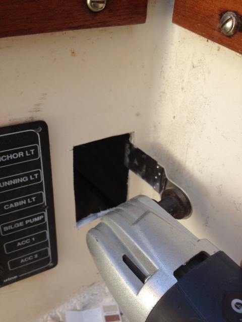
Multitool can create square cutouts with zero clearance
I used a multitool to make the cuts, which worked great because of the limited clearances. it would have been close to impossible to cut rectangular holes with the jigsaw
For the Galley I chose to mount the outlet in the side of the cabinetry, accessible to the kitchen without being too close to the sink. I crimped on connectors, Trying ring connectors the first time, but getting wiser when I found the outlets’ screws don’t back out the entire way. An auto wire stripper I found at harbor freight was very helpful. Their crimpers aren’t great, you generally have to use the next smaller size hole (blue for yellow) for a secure connection.
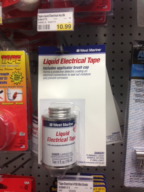
liquid electrical tape is handy for wet locations, sealing securely against moisture.
Over that I used some liquid electrical tape and then installed the outlets in the boxes and screwed on the covers.
Ground Current Fault Interrupt (GCFI) outlets are required for each run. These devices monitor power through them and if more than 30mA or so takes the wrong route, (through your body and wet feet to ground, for instance) they shut off the power in a millisecond. Standard 20A outlets can be used at the other locations but they need to be wired in properly, with grounds, and tested to make sure they are GCFI protected. I found some GCFI outlets at Orchard Supply
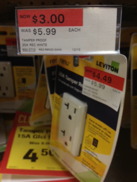
six bucks for a 20A GCFI outlet. You betcha. Gotta thank Leviton and Orchard supply.
that were being discontinued. Leviton had made some custom sized outlets designed to work with special décor plates that hide their screws. They didn’t catch on because the devices are nonstandard. the GCFI outlets were going for just $6 and their non GCFI outlets were $3 with the cover plates discounted to a buck. That clinched the decision to install four outlets instead of two!